 |
 |
| Alu C-Hub Suspension Option Set, Rear |
|
 |
| |
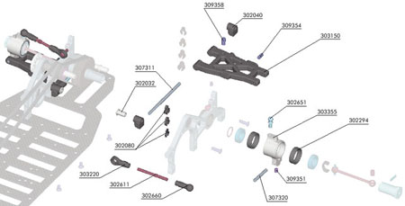
| C-Hub Suspension Option Set, Rear - Assembly |
(click to enlarge)
|
|

|
The new optional C-hub suspension is a great new tuning option to set up your T1 for different racing conditions. Before you mount the new C-hub suspension, dismount the entire rear suspension on the car, and also dismount the left rear bulkhead. |
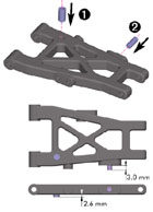
1. Thread a #309358 (SB M4x8) downstop adjustment screw into the rear lower arm. It must protrude 2.6 mm below the arm. This screw needs to be accessible from the top of the arm.
2. Thread a #309354 (SB M3x8) shock mounting screw into the middle hole located on the outside of the arm. It must protrude 3.0 mm.
Repeat for the other arm, making sure to mirror the screw placement. |
(click to enlarge)
|
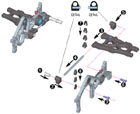
1. Insert a #302032 aluminum nut into a #302040 nylon lower suspension holder (front -with the CLOSED hole).
2. Mount the lower suspension holder (front) to the bulkhead using a #309335 (SH M3x10) screw. Do not tighten the screw; leave the holder loose.
3. Position the inside end of the #303150 rear lower arm in the rear bulkhead. Slide a #307311 pivot pin through the holes in the rear lower arm.
4. Put the pivot pin in the mounted lower suspension holder (front).
5. Mount a lower suspension holder (rear -with the CLOSED hole) onto the pivot pin.
6. Mount a lower suspension holder (rear) on the bulkhead using a #309335 (SH M3 x 10) screw.
7. Install the #302080 wheelbase clips onto the pivot pin. Use only three clips (one each of 4mm, 3mm, and 2mm) on each arm. The initial setting is to instal two clips (3 mm and 2 mm) in front of the arm, and one 4 mm clip behind the arm. For information on wheelbase adjustment, refer to the Set-Up Book.
Note: If you find that the arm does not move freely after installing the clips, remove the 4mm clip, lightly sand one side, and reinstall. Repeat this until the arm moves freely with all three clips installed.
8. Install the #302080 clips between the bulkhead and the mounted lower suspension holder (front) to set rear toe-in.
For information on rear toe-in, refer to the Set-Up Book.
The initial setting of rear toe-in is to install 2mm clip on the front holder.
The clips represent approximately these values:
1mm clip =1 °toe-in
2mm clip =2 °toe-in
3mm clip =3 °toe-in |
(click to enlarge)
|
1. Mount the whole left rear suspension assembly
bulkhead to the chassis using the #309343 (SFH M3x6) screws. Place the end of the rear alu suspension holder
into the cavity of the lower suspension holder (rear).
2. Thread the #309335 (SH M3 x 10) screw into the rear alu suspension holder. |

(click to enlarge)
|
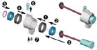
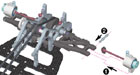
1. Insert two #302294 nylon ball-bear bushings into the rear uprights from both sides until they seat firmly.
2. Slide a #309054 (BB 10x15) ball-bearing onto the wheel axle.
3. Insert the wheel axle through the rear upright until the bearing seats in the nylon bushing. Note the direction of installation from the diagram.
4. Slide another #309054 (BB 10x15) ball-bearing onto the wheel axle. Press the bearing into the rear upright, making sure that it seats properly in the nylon bushing.
5. Fasten the wheel axle to the rear upright by installing a snap ring in the groove in the wheel axle (near the drive shaft joint). To make installation easier, place the hex portion of the wheel axle flat on a table. Put one end of the snap ring into the groove on the opposite side of the wheel axle cutout, and use a slotted screwdriver to work the rest of the clip into the groove.
6. Thread a #302651 ball end to the top of the rear upright, in the inner position.
7. Thread a #309351 (SB M3x4) screw into the bottom of the rear upright. Do not tighten fully.
Repeat for the other side. |
(click to enlarge)
|
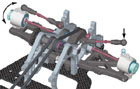
1. Place the driveshaft plastic cap into the diff outdrive slots. Insert the rear assembly into the end of the front lower arm. Align the hole in the bottom of the rear upright and holes in the arm.
2. Slide a #307320 pivot pin through the aligned holes. The flat spot on the pivot pin must be towards the bottom. Tighten the #309351 (SB M3x4) screw until it is tight on the pivot pin.
The rear upright should move freely. |
(click to enlarge)
|
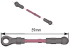
Assemble the rear turnbuckles by threading ball joints onto the ends of the spring steel turnbuckle.
Note:The turnbuckle has a CCW thread on one end and a CW thread on the other end. Adjust the turnbuckles to
a length of 59 mm, measured end-to-end. |
(click to enlarge)
|
Snap the turnbuckle ball joints onto the balls on the rear uprights and the adjustable ball ends in the rear bulkheads.
The suspension arms must be able to fall freely when lifted up then dropped. If there is any binding that prevents the arm from falling freely, remove the ball joint from the ball and lightly squeeze the ball joint with a pair of pliers.
Remount the ball joint and check the arm again. Repeat this process until there is no more binding. |
(click to enlarge)
|
| Instruction Sections |

 |
|
|
|
|
|
|