 |
 |
News  General General
XRAY Column #64 - Making the T4, Part 1 |
|
 |
| |
|
|
| Several RC magazines around the world have asked us to write a monthly column. With the kind permission we will re-publish the column at our web site too so all of the XRAY fans can read the latest news and behind the scenes information. Enjoy. |
|
(click to enlarge) |
|
|
|
Martin Hudy, XRAY T4 designer:
Every year, in preparation for the new indoor season, XRAY produces a new touring car that incorporates the advances and ideas learned over the previous yearâ™s races. We always wonder how we could possibly improve for future models, or if we have fully optimized the design. In the highly competitive electric touring car racing environment, however, development never stops. No sooner does one company raise the bar for performance, than the other companies are right there to follow suit or push the envelope even further. It is critical as a company to stay focused and concentrated all the time in an effort to lead the pack. This philosophy is what is what lead us to the all-new T4. |
|
(click to enlarge) |
|
|
|
| The design process started already early in December 2011, just few weeks after launching the T3â™12 version. The T3â™12 was a significant improvement over the 2011 version and the first races were very successful. The only times we seemed to struggle were on super high traction tracks such as the first ETS in Germany. As a solution, I immediately reacted with a new thinner 2mm chassis and 1.6mm top deck that were successfully tested and used at the Charity race in Italy. We found that the 2mm chassis made the car easier to drive in high traction conditions and did not make the car as susceptible to traction roll as with the standard 2.5mm chassis. Little did I realize that I had already begun taking steps towards the next XRAY touring car platform. |
|
(click to enlarge) |
|
|
|
I had been feeling for some time that we would need to attempt a different approach in order to reduce traction rolling in extreme traction conditions, yet still be able to increase steering and improve corner speed. Before doing anything with the long proven suspension I first wanted to experiment with weight distribution, chassis flex and primarily CG. My theory was that lowering the CG would reduce roll, thereby increasing traction and corner speed. Now I needed to test that theory.
With a clear idea of the goals we wished to achieve I had an option to go with something completely new or just to go step-by-step using the existing car as a test platform for new ideas. As we had only several months left to the start of the 2013 winter season, the logical choice was to start with the existing car. I still did not expect that the end result would be an all-new platform with a majority of the parts being redesigned, but that is the beauty of development. You start with a simple idea and you never know when and how it will end up. |
|
(click to enlarge) |
|
|
|
| After some initial thoughts and clearly set goals I found finally some time at the beginning of the December to sit in front of the computer and start to draw the first parts. The highest positioned parts on the car were the shock towers and shocks so those were the first parts I wanted to drastically lower. After several design revisions I ended up with new shock tower and shocks lowered by 15mm. To avoid any possible problems I wanted to keep the same volume of oil to ensure that the shock will function as smoothly as the current car. I proceeded to calculate the total internal volume of the current car and adjusted the diameter of the shock body to compensate for the reduced length. Using the same volume of oil in the shocks also reduced the number of variables in the test, allowing us to better pinpoint which changes made improvements. |
|
(click to enlarge) |
|
|
|
| I also wanted to test short springs, but again, I did not want to go directly into unknown territory and therefore I made two alternatives. I would use short springs with standard shock collars and standard springs with lowered collars, allowing me to quickly change and test back to back two alternatives on short shocks. To have a very concise idea and accurate feedback on the short vs long parts I also made special shock towers so I could test and compare back to back short vs. long shocks. When I showed the 3D drawings of the shocks to Juraj, he was not 100% sure. He liked the idea of lowering the CG but he was unsure about short shocks, as it was a little bit risky. Since I had a âśgreen lightâť on this project from Juraj and no limits for prototyping, I decided to spend the resources on producing these short shocks to test that my theories were correct. This was a risky move for me, as the investment for prototyping was significant. If my theories did not work out as I projected, it would make it harder to gain approval for future â�riskyâ™ projects. |
|

(click to enlarge) |
|
|
|
| After preparing the lowered parts to bring the CG down in the car, I next focused on further centralizing the mass. In theory, bringing the mass closer to the centerline should improve the chassis roll characteristics. I had been puzzling for some time on how to accomplish this, as I feared that changing the bulkheads would force a complete redesign, as well, of the spool and diffs. Once I had an opportunity to sit and think clearly on the situation, the solution became obvious. I would simply design new bulkhead bushings which were offset to accommodate the new bulkhead positions, making other changes unnecessary. For the initial testing I could have the existing bushings CNC modified but would achieve only -3mm instead of the 6mm targeted overall, but since I did not want to rush the mould change I decided to go into this âśsemi-solutionâť which would provide at least some feedback and give me direction for the final changes. |
|
(click to enlarge) |
|
|
|
The narrower bulkheads automatically meant new front and rear shock towers, so the prototypes we made for first initial testing of short shock parts were scrapped. These interim towers would be scrapped as well once we went the full -6mm narrower for the bulkhead position. To ensure the same conditions for testing I wanted to keep the suspension geometry exactly same, which meant that upper bulkhead clamps had to be made new with offset roll center positions to simulate the same roll center positions as the T3â™12.
While working on the bulkheads I did not only change their positions but completely redesigned the shapes primarily to make the car more flexible in both front and rear. The reason for more flex in the rear was to get more rear traction and in the front to get more steering and forward traction, which we were slightly missing on the last T3 car. I wanted to simplify the bulkheads as well, and therefore I designed the lower suspension bulkheads so that we could use same bulkhead design in all 4 corners. With the new shape I could achieve the flex that I was looking for. The rear bulkhead mounting points were moved more to the rear which allowed the chassis to flex more between the mounting points of the suspension bulkheads and layshaft bulkheads for more rear traction. The mounting points in the front were moved further back to achieve more flex in the front part of chassis for more forward traction. A secondary benefit of this redesign of the bulkheads was a significant reduction in their weight.
The last bulkhead to be redesigned was the motor mount. Since everyone runs only the brushless motors today I decided on a radical design change. By mounting the motor using 2 screws in the lowest position, I was able to remove the majority of the material from the motor mount. |
|
(click to enlarge) |
|
|
|
I wanted to be sure that this motor mount would be beneficial for car performance and therefore I made two different motor mounts to test. The first motor mount would hold the motor in the lower position while the second one would mount the motor in the traditional center position. With these two different prototypes I could quickly change the bulkheads and test the difference back to back. After some initial sketches of the lowered motor mount another idea came to my mind - to make the mount fully separated from the central bulkheads, which would allow me to use identical layshaft bulkheads on the right and left side.
My initial enthusiasm was cooled after the first tests when I kept breaking the spur gear as a result of excess flex. I recognized that the motor mount was fixed to the layshaft bulkhead with just 1 screw so, without much thinking about complicated solutions, I drilled an extra hole and installed a second screw which immediately solved the problem. From that moment onwards there was no spur gear problem anymore. I was surprised that a small part like the motor mount could have such significant influence on the traction. The comparisons using the same track conditions with the standard motor mount and this new lowered mount validated my theories regarding the motor mount system. |
|

(click to enlarge) |
|
|
|
Over the years we have spent a lot of time on the steering system, trying and testing plenty of different combinations, different ideas and different parts. We had made a lot of progress in recent years, but we still felt that there was something missing or something not completely perfect with our steering system. Specifically, when I was observing our cars on carpet, I saw that we have a lot of steering on corner entry (which was good), but then the car kind of â�stoppedâ™ as it slowed down and then in the middle of the corner the car started to push.
After thinking and discussing the potential causes of our problem I came up with a very simple idea - to test a different servo linkage mounting position. Our main observation was that on the T3 when you set-up steering you have 25 degrees, but in reality it is always more as the force from the wheel touching the surface will overpower the servo saver and therefore in reality would steer more(allowing as much as 33degrees of throw). This excess steering angle resulted in the car having the âśstopâť effect in the corners. The driver would feel as though they have lots of steering, but it was only an illusion. |
|

(click to enlarge) |
|
|
|
The initial idea to test and prove this theory was to glue backstops on the C-hub (simple alu shims) which would stop the steering block at exactly 25 degrees. In the first test I felt initially that the car had less steering but since the âśstopâť effect was removed I was able to reach higher cornering speeds and the car was much easier to drive which of course translated into improved lap times. With our theory proven, I now had to figure out how to change the steering system to limit the steering at 25 degrees without allowing the steering block to touch the C-hub. The solution was very simple indeed. I added a large mounting bushing on the central alu steering plate where the servo linkage is mounted. When the steering reaches 25 degrees the alu shim works as a backstop and limits the steering throw to the maximum 25 degrees.
The entire testing phase of the various prototypes with the team was extremely demanding. We suffered through difficult assessments, and frustrating hurdles, but overcame them to arrive at a result that we were enthusiastically satisfied with. Some more insights about the real track tests and some behind the scenes information will be disclosed next time in the second part of this column.
Martin Hudy
|
|

|
|
|

(click to enlarge) |
|
|
(click to enlarge) |
|
|
|
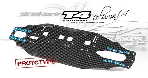
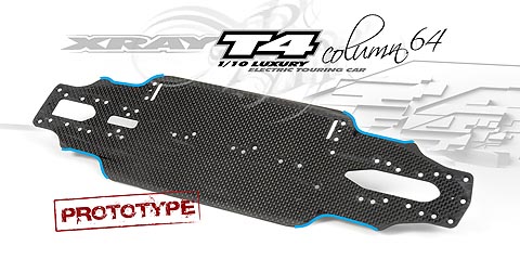
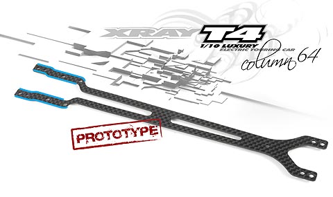
V1 chassis had the bulkheads only 3mm narrower as the bearing bushing mold was not ready yet. In this chassi test we wanted to understand how the different bulkhead mounting behaves at the track. We wanted to understand what is the difference between mounting diff bulkheads in the center of diff position and when they were eccentric. We found out that what was our tought, was really true. When the mounting positions in the rear were moved to back, we get more rear traction and in the front when we moved the bulkheads more to the front from the center, we got more front traction and in-corner steering. We also tested separate split arm holders in the rear-rear and front-front but this made the car too twichy and we realized that those blocks have to be make from one piece.
First prototype chassis(V1). To allow as much flexibility as possible for testing options, as well as to reduce the number of variables in the test, we decided to test different bulkheads and bulkhead mounting positions using one common chassis. Testing was much easier in this way because when we wanted to compare two different mounting positions, we did not have to change the whole chassis, but rather, remove and re-install a few screws to quickly change the bulkhead. This greatly increased the efficiency of the test sessions, as we saved time, material expenses and improved our test results by being able to compare different options quickly while keeping the introduction of new variables to a minimum. For the V1 chassis test, we narrowed the bulkheads by only 3mm, as the mold for the eccentric bushing for bearing support were not yet ready. The goal of this chassis experiment was to test and understand how the different bulkhead mounting positions and configurations effect how the car behaves on the track. We confirmed that the mounting positions of the bulkheads affected the chassis flex and resultant handling in precisely the manner we had anticipated. We also used the opportunity to test various configurations of lower arm mounts.
|
|
(click to enlarge) |
|
|
|
| Second prototype chassis(V2). Once we had confirmed the improvements due to bulkhead position, and after the eccentric bushings were ready, we were able to move the bulkheads to their final position (narrowed 6mm compared to the T3). At this point we were now prepared to test and assess chassis thickness. We tested 3 difference chassis thicknesses (2mm, 2.2mm and 2.5mm). During our testing we found the 2.5 chassis to provide ample steering, but that it was too twitchy. The 2mm chassis was the exact opposite. When we tested the 2.2 and found it to be a balanced compromise, we knew which direction we were going to go. With the easy part done, we proceeded to test to find the best chassis flex and width. We tried two different chassis widths (standard 94mm width and narrow 90mm). After testing on different track surfaces we came to the conclusion that we would keep the same chassis width as on T3 2012 because 90mm seemed to push during testing. The T3 2012 chassis shape worked perfect on carpet but we felt that for asphalt, we would need to get slightly more chassis flex for more steering and traction. After a quick trackside modification, we found that even though we had not improved upon our fastest lap time, the feedback from the testing team was that the car had increased steering, increased traction and was easier to drive. We also noted an improvement in the consistency of the lap times. In order assure that the best option was selected, we re-tested the car on carpet and again found that this new chassis shape and properties were an improvement. With this verified, we were confident that the chassis plate was ready. |
|
(click to enlarge) |
|
|
|
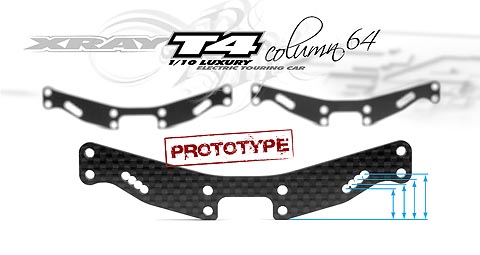
| The final design of the rear shock tower. This final design was tested final (V2) bulkheads and short shocks in order to precisely align the shock holes to achieve the desired shock angles. |
|
(click to enlarge) |
|
|
|
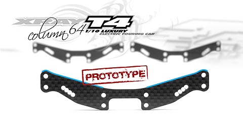
| This is a variant of the shock tower used during testing to allow the use of T3 2012 shocks on the T4 prototypes. This allowed us to quickly change the shock tower and shocks to evaluate the differences between long and short shocks in various track conditions. Shock mount positions were precisely located to maintain consistent shock angles. |
|
(click to enlarge) |
|
|
|
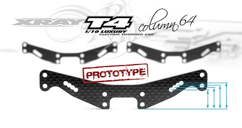
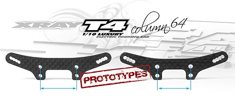
| The first prototype of the shock tower for T4 short shocks. This shock tower was used with V1 prototype which had bulkheads narrower by 3mm compared to the T3 2012. I attempted to keep the design as lean and light as possible, but chose to add additional material around the body posts to improve durability. |
|
(click to enlarge) |
|
|
|
Comparison of the V1 and V2 shock towers. V1 tower was designed to fit 3mm narrower bulkheads while V2 was designed to fit final 6mm narrower version.
|
|
(click to enlarge) |
|
|
|
| This is the first prototype top deck, designed to fit the V1 chassis with bulkheads narrowed by 3mm. The rear portion of the top deck was less stepped than that T3 2012 version. This version allowed for more flex and slightly more traction. This moved us in the direction we were hoping to achieve, so decided to eliminate the step altogether when we moved the bulkheads into their final position. |
|
(click to enlarge) |
|
|
|
| The first tests with narrower bulkheads required some handmade prototypes. With some initial uncertainty regarding the benefits of narrower bulkheads, it was necessary to limit the amount of changes made during early testing, as the prototype costs could escalate in a hurry. In order to remain objective about the performance impact of the narrower bulkheads, I had to keep the suspension geometry exactly the same as the existing kit. I would also need to maintain the existing roll center positions. To achieve this, without incurring the costs of custom prototype bulkhead clamps, we modified a set of the existing clams to reposition the inner camber link to precisely match the positions of the T3 2012. |
|
(click to enlarge) |
|
|
|
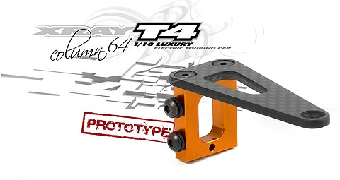
| The first prototype servo mount. Using the information learned during the development of the T3 2012 Central servo mount option piece, I was able to come up with a simple but effective servo mount solution that saw only minor modifications throughout the T4 design process. |
|
(click to enlarge) |
|
|
|
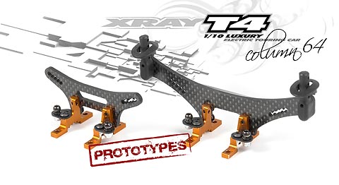
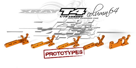
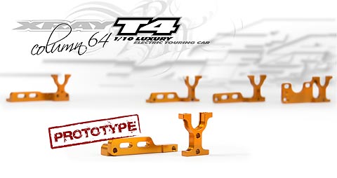
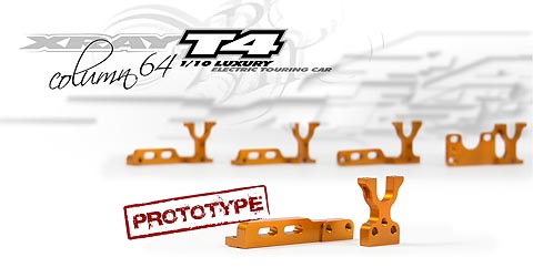
| Different designs and shapes of bulkheads. The 3 motor mounts on the right were designed concurrently in order to test and assess which option would be ideal. During back to back testing by the team in Scandiano, and at the Worlds Warm Up race, the designs were assessed and updated. The two pieces on the left were the result of the design update procedure. |
|
(click to enlarge) |
|
|
|
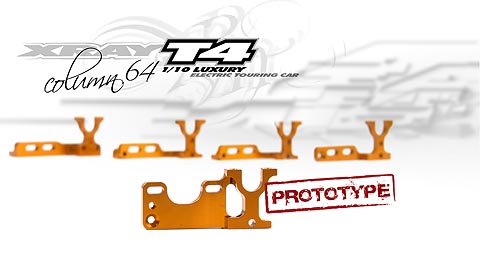
| 1. This was the first motor mount that I drove. The mounting position of the motor is the same as on the T3 2012 but it is lightened to save some weight and designed improved appearance. |
|
(click to enlarge) |
|
|
|
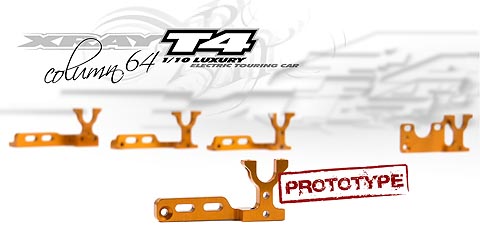
| After designing the first motor mount, I began to consider how I could make it even lighter. During the design process, I had 8 of the most popular motor designs arranged next to each other on my table. I recognized that the position and size of the mounting holes were identical for all 8 motors, and provided an opportunity to use a non-traditional layout for the motor mount. By using two screws in the lowest holes for the motor mount, we could reduce the amount of material in the motor mount, as well as drastically lower the CG of the mount. During testing, we also found that this new configuration also helped improve rear traction. |
|
(click to enlarge) |
|
|
|
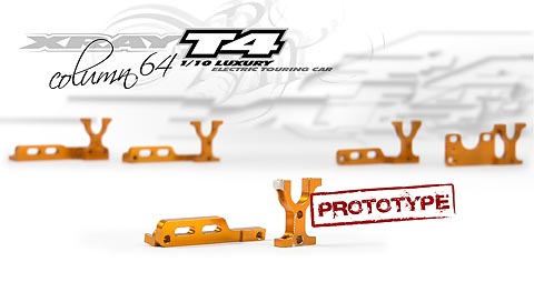
| Once I was satisfied with the method of attaching the motor mount to the layshaft bulkhead I began to focus on how to connect it to the chassis. With the T3 2012, we found that there was the possibility of introducing tweak after a crash. While the tweak was not severe enough to impact the majority of drivers, it was an area we felt could be improved upon. Experiences with the T3 led us to suspect that the screw connecting the mount to the chassis could be the cause of this tweak. A brainstorming session on how to eliminate this tweak-point led to the use of an M3 nut instead of tapping the aluminum material for the motor mount-to-chassis attachment point. After several crashes during testing, we were unable to identify tweak in this area, so incorporated this feature in the final design. We feel that this is a feature that can benefit drivers of all levels. |
|
(click to enlarge) |
|
|
|
| Since we were working with a clean slate and were designing all new bulkhead components, we decided to make every effort to commonize them as much as possible. I was able to identify that, by separating the motor mount from the layshaft bulkhead, we could use a common design for both layshaft bulkheads. During testing, we discovered an added benefit as the car had more traction and felt easier to drive. |
|
(click to enlarge) |
|
|
|
| Even though I was happy with the performance of the separate motor mount, I was not happy with the durability. Several times during testing excess flex caused damage to the spur gear. I did not want to abandon the idea of the separate motor mount, so instead it would be necessary to make it more durable. By adding a second screw to connect the layshaft bulkhead and the motor mount, as well as increasing the material thickness, the excess flex was removed and the spur gear damage was to have been eliminated. |
|
(click to enlarge) |
|
|
|
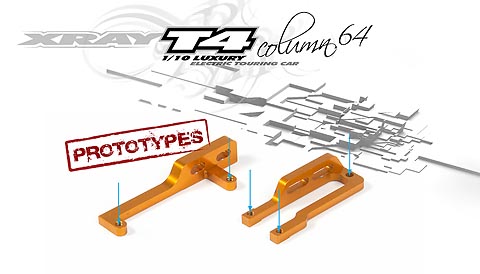
Juraj also proposed an alternate idea, to have the motor mount fixed totally independent of the layshaft bulkheads in order to maximize flex and totally eliminate tweak. The first concept was to use two connection points directly on the chassis centerline to attach the motor mount. Tests revealed that this configuration allowed for potential damage to the spur gear. This variant also stiffened the center portion of the chassis excessively and reduced rear traction. In-corner steering was improved, but the car became very difficult to drive.
We attempted to reposition the motor mounts to reduce the spur damage. We tried using two fixing points near the layshaft bulkheads plus a screw and nut along the centerline. This improved the durability, but the overall handling was not satisfactory. We do see strong potential in this unique design and will continue to investigate and develop this concept further.
As always, we will continue to test and evaluate new solutions to keep XRAY at the front of the pack.
|
|
|
See you around the tracks!
Enjoy the ride and â�til next time,
Martin Hudy
XRAY Designer
|
| Archive: |
|
Column #1 - Behind the Scene Stories
Column #2 - Worlds Flashback
Column #3 - T2'007 Debut
Column #4 - Designing the T2'007
Column #5 - Worldcup Review and NT1 Testing
Column #6 - Developing and Designing the NT1
Column #7 - Developing and Designing the NT1 - Part 2
Column #8 - Back to the Races
Column #9 - XT8 Truggy Development
Column #10 - Touring Car Development
Column #11 - Bling-bling Mentality
Column #12 - Hot Summer Washout
Column #13 - New Electric Touring Car
Column #14 - Off-road Development
Column #15 - My micro love
Column #16 - Back in the Dirt
Column #17 - Worlds Preparations
Column #18 - 808 Tests & Stress
Column #19 - Excited for the Worlds?
Column #20 - Statistics, Expenses Sheets, Production Analysis, Calculationsâ¦
Column #21 + Column #22 - Euros + Euros + Worlds
Column #23 - The Busiest Season Ever
Column #24 - In Between the Worlds
Column #25 + Column #26 - Well Developed or Overdeveloped?
Column #27 - Back to The Future
Column #28 - 2009 Kick-off
Column #29 - Crazy what?
Column #30 - Last indoor race of the season
Column #31 - Getting into summer season
Column #32 - Heading for the Euros
Column #33 - Testing - Always last minute, always new ideas
Column #34 - European Champion - title celebration
Column #35 - Time to move on
Column #36 - National Heroes
Column #37 - 2010 ready
Column #38 - Decade of Triumph
Column #39 - 2010 Racing Calendar
Column #40 - DHI, ETS & NĂĽrnberg Show
Column #41 - World Championship Practice
Column #42 - EC indoor, EC 1/12, Silverstate, LRP Masters, Neo
Column #43 - Nationals All Around
Column #44 - Warm Warm-ups, Challenging Challenges
Column #45 - Electric Touring Worlds 2010
Column #46 - Team XRAY - World Champion!!!
Column #47 - Summer Vacation, 30x USA Champion Title
Column #48 - T3 Saga Continues
Column #49 - RX8 â“ What? How? When?
Column #50 - The Making of the RX8 â“ Part II
Column #51 - Shake It, Baby, Shake It...
Column #52 - Racing Season â�11 Full Running
Column #53 - From On-road to Off-road
Column #54 - Testing and Once Again⦠Testing
Column #55 - Half of the EC Championships â“ Done!
Column #56 - Summer is Goneâ¦Euros are Done
Column #57 - Never-ending Development
Column #58 - From XB8 to XB9
Column #60 - 2012 Season Running
Column #61 - Crazy Months
Column #62 - ETS Champion
Column #63 - 2012 Racing Summer Summary |
|
|
|
|