 |
 |
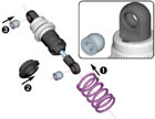
| XRAY Shock Absorber - Set 4-Step (2) |
|
 |
| |
| Instruction Manual For XRAY Shock Absorber |
(click to enlarge)
|
XRAY Shock Absorbers
|

|
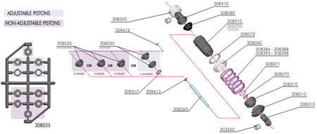
Properly functioning shocks are one of the most important factors in the performance of your car. This XRAY shock set allows you to build four externally-adjustable or non-adjustable shocks. Both adjustable and non-adjustable shocks feature XRAY's unique keying system that positively locks the pistons to the shockrods.
When removing the parts from the frames, carefully remove the parts, then VERY carefully trim any excess flash with a sharp knife. We advise using extra-fine sandpaper to gently grind all small flashes. The side walls of the pistons must be perfectly round and smooth for proper operation. |
(click to enlarge)
|
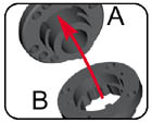
Adjustable Pistons
Cut all shock parts free from the parts trees, carefully trim any excess flash, and lightly sand if necessary.
The upper piston with holes (A) has a small tab that must exactly fit into one of the notches in lower piston (B). |
(click to enlarge)
|
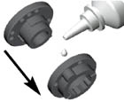
Apply a drop or two of shock oil to the piston pieces. Press upper piston (A) into lower piston (B) as shown. Be sure to insert the upper piston into the lower piston so the tab sits in the notch. |
(click to enlarge)
|
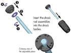
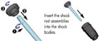
Assemble all four adjustable piston assemblies and shock rods as follows:
1. Press #309413 (C 2.3) E-clip into lower groove of shock rod.
2. Place #309317 (S 3.2) washer onto shock rod atop C-clip.
3. Press piston assembly onto shock rod, aligning flat in pistons with flat on shock rod.
4. Press #309412 (C 1.9) E-clip into upper groove of shock rod.
|
(click to enlarge)
|
Non-Adjustable Pistons
Cut all shock parts free from the parts trees, carefully trim any excess flash, and lightly sand if necessary. Assemble all four non-adjustable piston assemblies and shock rods as follows:
1. Remove all four 3-hole non-adjustable pistons from the parts frames.
2. Press #309413 ( C 2.3) E-clip into lower groove of shock rod.
3. Press 3-hole piston onto shock rod, aligning flat in piston with flat on shock rod.
4. Press #309412 (C 1.9) E-clip into upper groove of shock rod. |
(click to enlarge)
|
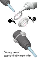
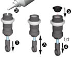
Perform for all four shock bodies:
1. Apply a drop or two of shock oil to the inside edge of the #308072 (O12.1x1.6) O-ring and insert it inside the groove of a #308040 threaded shock adjustment collar.
2. Thread the adjustment collar onto the shock body. |
(click to enlarge)
|
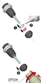
1. Insert the larger #308071 (O 5x1) O-ring onto the shock body, until it seats on the extended end of the shock body.
2. Lubricate the small #308070 (O 3.1x1.6) O-ring with a drop or two of shock oil. Taking care not to rip or damage the O-ring, slide it over the extended end of the shock rod.
3. Install the end-cap on to the bottom of the shock body. Lock it in place by pressing it on, then turning it about 1/8 of a turn CW. For easy assembly, use the #183010 HUDY Assembly Tool.
|
(click to enlarge)
|
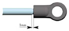
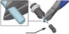
Grip the top of the exposed thread of the shock rod with side-cutting pliers and thread the ball-joint onto the shock rod until the joint ends approximately 1mm from the end of the thread. See the illustration.
|
(click to enlarge)
|
Hint: Pre-thread the ball-joint using an M3 screw. This will make it easier to thread the ball-joint onto the shock rod. |
(click to enlarge)
|
1. Fully extend the piston rod so that the piston is at the bottom of the shock body.
2. Hold the shock upright and slightly overfill the shock body with oil.
3. Let the oil to settle and allow the air bubbles to rise to the top. Slowly move the piston up and down until no more air bubbles appear.
4. Move the piston out until it is about 1/2 way out of the shock body.
5. Place the rubber bladder on top of the shock body. Some oil should spill out.
6. Move the piston out very slightly so the bladder is sealed against the top of the shock body.
|
(click to enlarge)
|
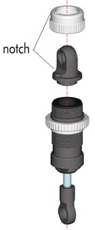
Place the top pivot-point on top of the bladder. Note the key notch on the top-pivot point.
Place the #308350 aluminum collar over the top pivot-point, and thread it fully onto the shock body. Take care to match the key notch on the collar and top-pivot point. More excess oil may escape.
Check to make sure the shock absorber functions properly. The shock must move up and down freely with only "hydraulic" dampening. When you push the shock rod into the shock body then release it, the shock rod should not extend out by itself. If there is any air still left in the shock, open it again and start the bleeding procedure over.
Shock length adjustment:
It is VERY important that the two shocks on each end of the car (front or rear) are equal lengths. Adjust the length of the shock by tightening or loosening the ball-joint on the shock rod. |
(click to enlarge)
|
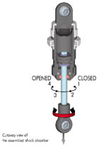
Damping adjustment:
If you built the adjustable shocks, fully extend the shock rod and turn it slightly to lock the piston in the shock body. Turning the shock rod fully CCW aligns 4 holes in the pistons (softest damping). Turning the shock rod fully CW aligns one hole in the pistons (hardest damping). The shocks have four settings, each of which can be felt by a little "click".
Set all four shocks to position 3 (3 holes open -- medium) |
(click to enlarge)
|
Final shock assembly:
1. Install the springs on all four shocks.
2. Secure the spring with a spring cup.
3. Use pliers to install two #303240 balls in each shock; one in each of the upper and lower eyelets. |
| Instruction Sections |

 |
|
|
|
|
|
|